¶ Introduction
In order to give users a good printing experience, QIDIStudio provides the best calibration guide for novice users. The specific calibration guidance content is divided into the following three types:
-
flow ratio
-
Pressure advance
-
Maximum volume velocity
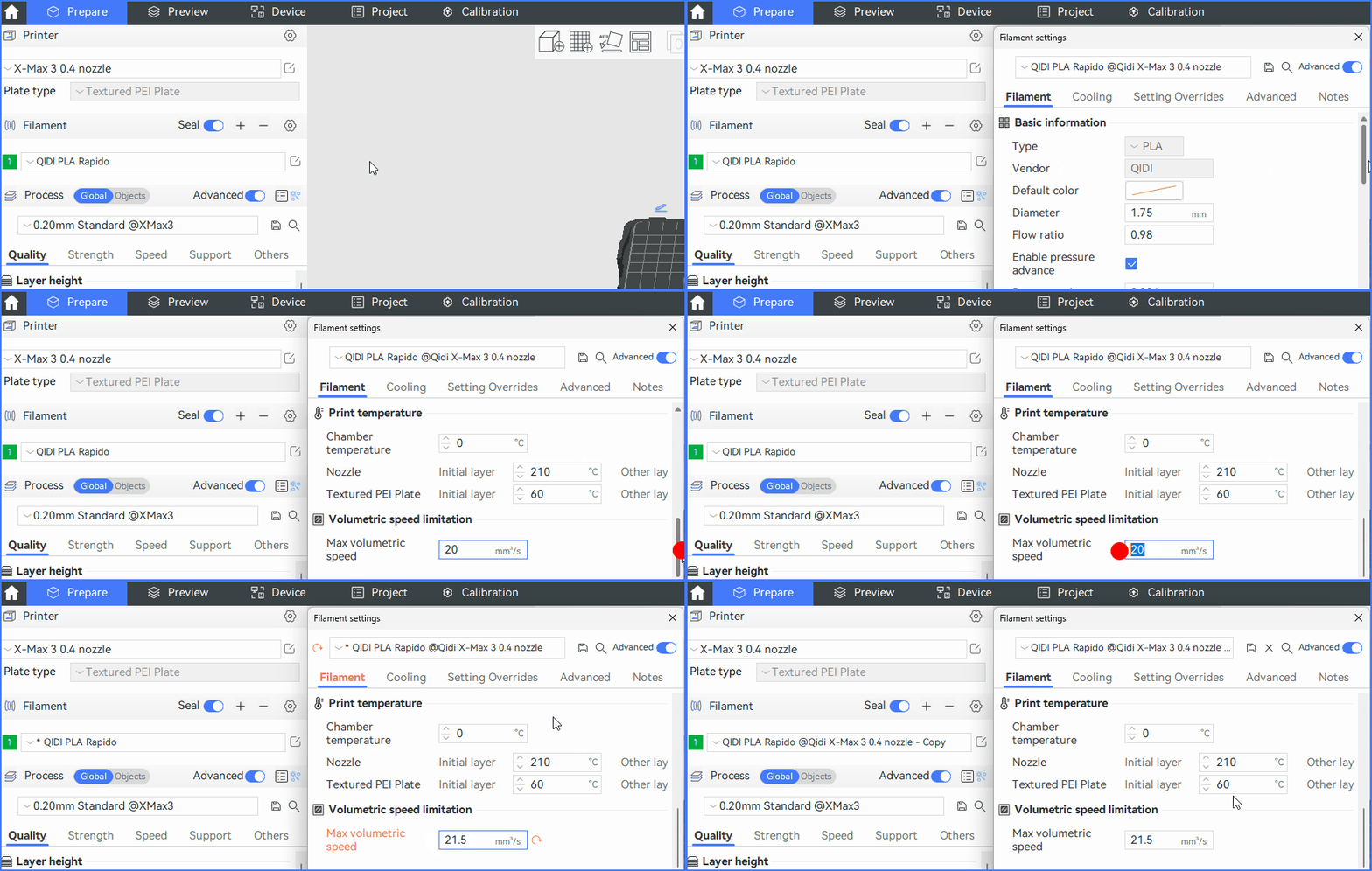
Don't worry, in order to improve the user experience, QIDIStudio will greatly simplify the calibration process, only need the user to click a few buttons, modify the corresponding value, you can easily complete the entire calibration process.
¶ Flow ratio
When the user uses the official filament, printing with the software's default configuration parameters performs well in the vast majority of print cases. These default configuration parameters were summarized by the experimenter through many print adjustments.
¶ When do I need flow calibration?
If the user experiences the following signs and other reasons for uncertainty during the printing process, a flow calibration may be considered.
-
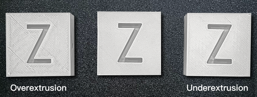
Oversqueeze.
The printed model has excess material, spots, or layers that look too thick, which can be caused by over-extrusion. -
Insufficient extrusion
The model will show signs of missing layers, gaps in the surface, or inadequate filling. This is caused by the printer not extruding enough filaments during the printing process. -
Poor surface quality
When the printed model looks rough and uneven, it may be due to incorrect flow rates. -
Weak structural integrity
The printed model is prone to breaking or not looking strong enough, which can be due to insufficient extrusion or poor layer adhesion. -
When using third party filaments
¶ Calibration process
Calibration consists of the following two processes: Coarse calibration and Fine calibration.
Generally, you can use coarse calibration first to get a rough range, and then fine-calibrate to get an exact value. If you feel that the process is too cumbersome, you can also print directly using the value obtained by coarse calibration, and you can also get a good print result.
Before calibration, you need to select the printer you are using, the filament you want to calibrate, and the process parameters. The corresponding parameters are selected and adjusted in the upper left corner of the Calibration page.
After adjusting the above parameters, directly click the Coarse calibration on the page. The Coarse Calibration guide page will be displayed.

¶ Coarse calibration
-
After entering the coarse calibration guide page, you click the Calibration button at the bottom of the page. Model selection and slicing are done automatically by the program.
-
Send the GCode obtained by slicing to the printer through the network or USB flash drive for printing.
-
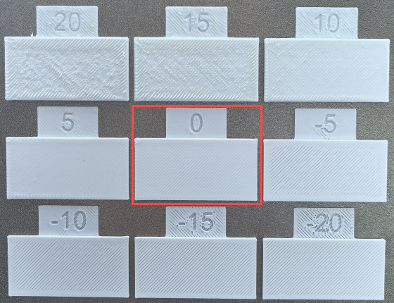
After successful printing, you will get the model as shown in the picture below, choose the number with the smoothest surface. As you can see, the model with the number "0" has the smoothest surface, so the coarse calibration yields a value of 1+0.00=1.
-
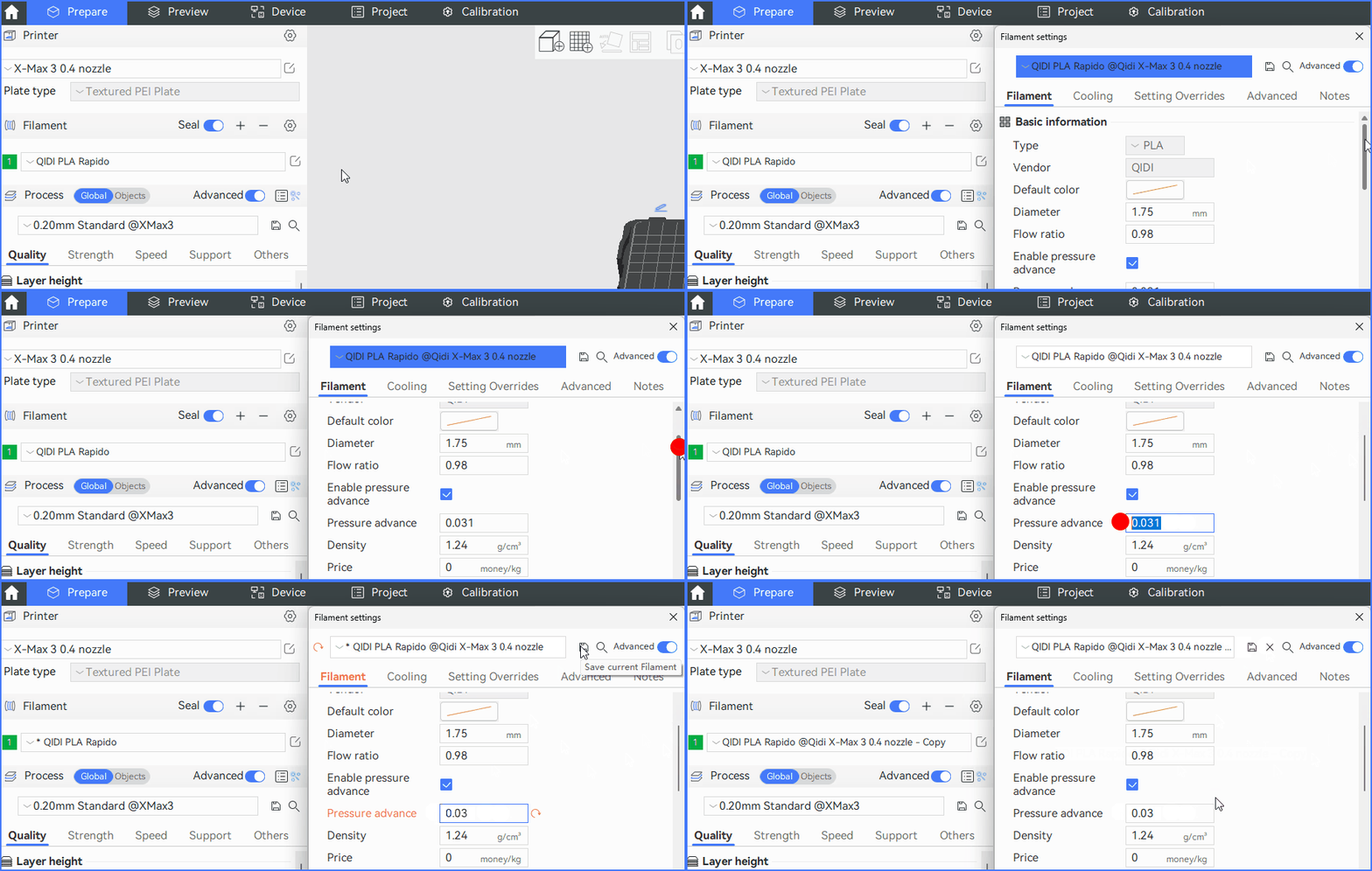
Return to the preparation page, open the filament parameter edit box, modify the flow ratio value to 1, and then click Save Configuration.
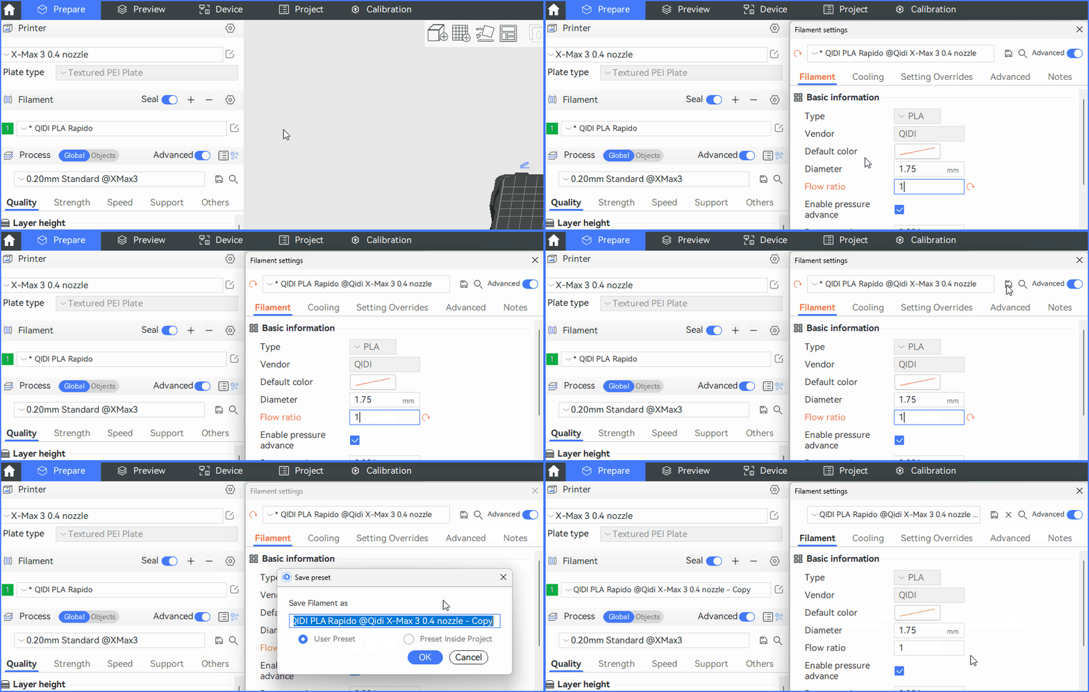
Note: The specific formula for calculating the flow ratio: 1 + (value/100).
¶ Fine calibration
Fine calibration is based on coarse calibration.
-
Open the fine calibration page and enter the results of the above coarse calibration operation in the input box for "Flow Ratio".
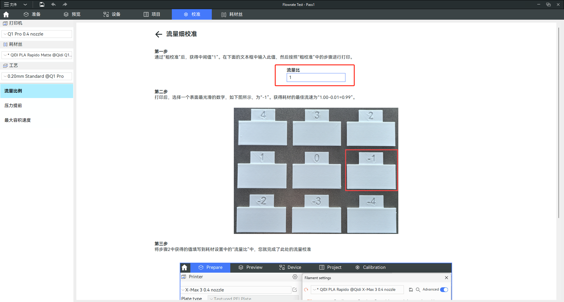
-
Click the Calibration button at the bottom of the page. The selection of models and slices is done automatically by the program.
-
After successful printing, you will get the model as shown in the picture below, choose the number with the smoothest surface. As you can see, the model with the number "-1" has the smoothest surface, so the coarse calibration yields a value of 1+(-1/100)=0.99.
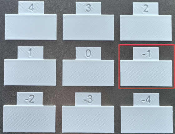
-
Return to the Preparation page, open the filament parameter edit box, modify the flow ratio value to 0.99, and click Save Configuration.
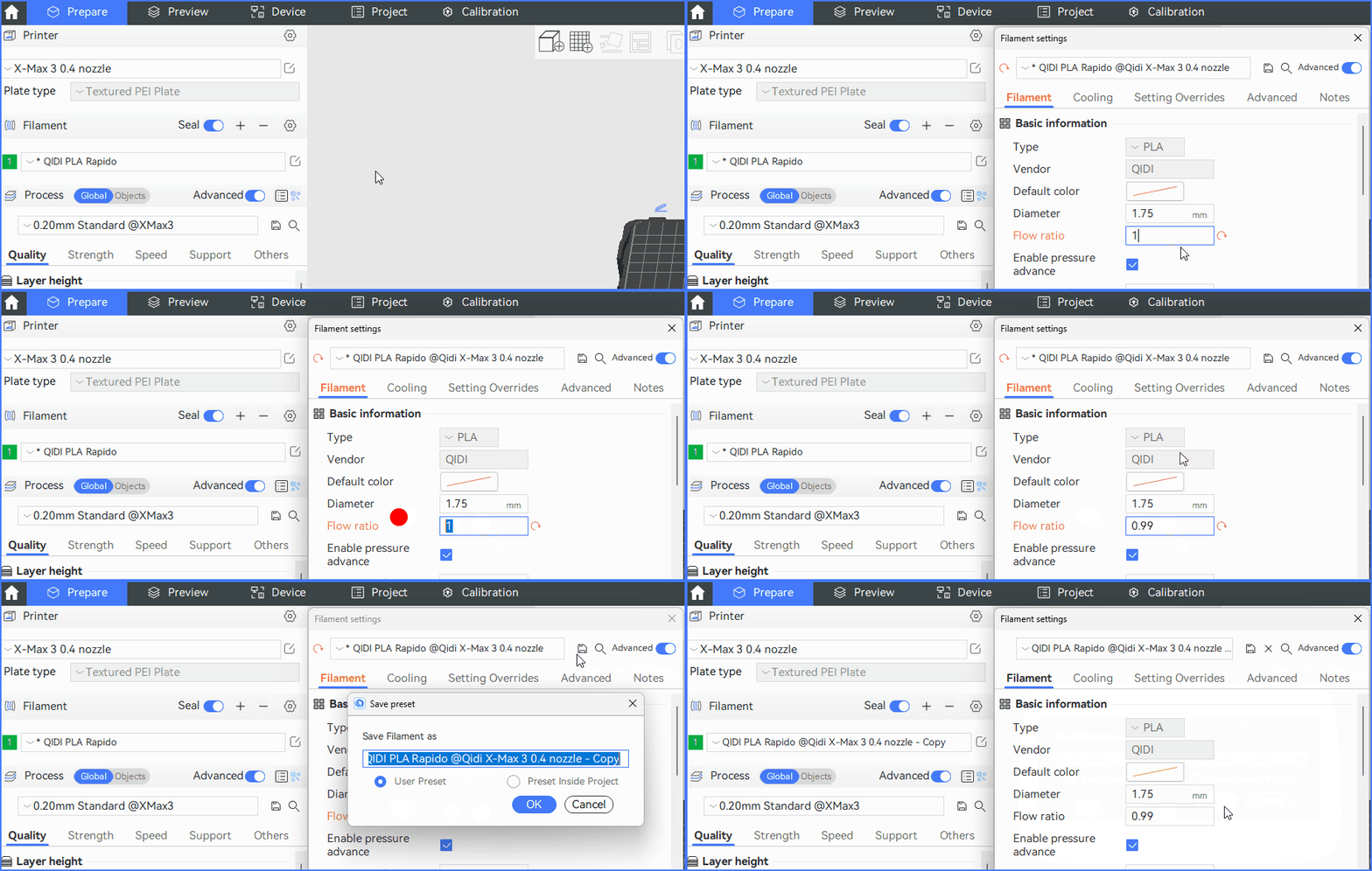
Note: The calculation formula for fine calibration is consistent with that for coarse calibration.
¶ Pressure advances
¶ What is Pressure Advance Calibration?
From a fluid mechanics point of view, when a Newtonian fluid flows through a hole, it requires pressure, which is directly proportional to the flow rate.
Since the filament filament is not a rigid body, when the extruder starts extruding, the filament will be compressed to create pressure. The compression process will delay the response of the actual flow. This is because the extruder only provides the amount of filament that need to be extruded, not additional filaments.
¶ When is a pressure advance calibration required?
- Use different brands of filament, or if the filament are damp.
- Nozzles are worn out or nozzles of different sizes are replaced.
- Use different printing parameters such as temperature and line weight.
¶ Calibration operation
We provide 3 pressure advance calibration modes, to enter the corresponding calibration mode, you only need to click the corresponding button at the bottom of the page.
- PA line
- PA pattern
- PA Tower
¶ PA Line
-
Enter the initial K value, end K value, and value step in the input box.

-
Click the Calibration button at the bottom of the page. The software will automatically generate the model and slice it. All you need to do is send the slice file file to the printer for printing. The printed model is shown in the figure below.
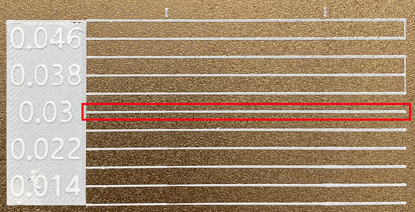
-
As you can see in the image above, the line segment with a label of 0.03 is the smoothest. Enter the corresponding value into the software for saving.
¶ PA Pattern
Consistent with the operation of the PA line. The printed model is shown in the figure below.
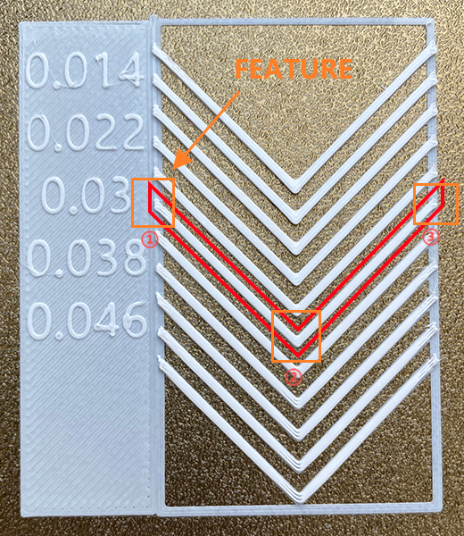
Select the value corresponding to the smoothest part of the figure and modify the filament parameters.
In the model above, there are three feature areas to look at:
-
In zones 1 and 3 of the diagram, when the pressure advance value is too small, material accumulation will occur and the endpoints will exceed the bounding box. When the pressure advance value is too high, there may be a shortage of segments and the breakpoint cannot reach the bounding box.
-
In area 2 of the figure, when the pressure advance value is too small, there may be material accumulation, which may cause excessive overflow of corners during the actual printing process. When the pressure advance value is too high, thread loss may occur. In actual printing, it causes the corners to round and cause missing lines.
¶ PA Tower
This is consistent with the above two calibration methods.
This method is more cumbersome than the above two methods. A ruler is required.
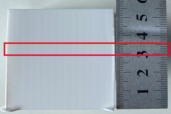
Each corner of the model needs to be observed and aligned for calibration. For every 5 mm increase in height, the pressure advance increases in step increments. If the pressure advance is too small, excessive squeezing will occur in the corners. If the pressure advance value is too large, there will be rounding of right angles or even missing threads at corners.
After observing the best position for the effect, measure the height with a ruler and determine the height using proportions.
Use the formula to calculate the best pressure lead value:
Pressure advance = k_Start + floor(height/5) * k_Step
floor means round down.
Finally, the calculated value can be saved.
Note: Pressure pre-calibration is not available for PETG filament.
¶ Maximum volumetric flow rate
¶ What is Maximum Volume Velocity Calibration?
- Different filament have different maximum volume velocities.
- Nozzle material, diameter, printing temperature, etc., all affect the maximum volume velocity.
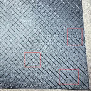
- When the maximum volume velocity is set too high and does not match the filament characteristics, missing lines may occur during the printing process, resulting in deterioration of the surface texture of the model.
This is a test designed to calibrate the maximum volume velocity of a particular consumable. This test will help you find the maximum volumetric velocity for your filament when the third-party filament type does not set the correct volumetric velocity in the filament settings.
¶ When is the maximum volume velocity calibration performed?
We have set the appropriate values in the software for the official filament. In the event of a later situation, the maximum volume velocity needs to be calibrated by the user:
- There are no filament configured by default (third-party filament added by yourself).
- Replace nozzles of different materials and diameters. The default print temperature has been changed.
- Missing lines, insufficient extrusion, or broken fills are found during the printing process.
¶ Procedure
-
On the Maximum Volume Velocity Calibration page, enter the minimum volume velocity value, the maximum volume velocity value, and the step size value.
-
Click the Calibration button at the bottom of the page. The software will automatically generate the model and slice it.
-
Print the model to get the model as shown below.
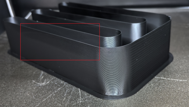
It can be observed that at a certain height, the model begins to show the missing state. There are two ways to measure maximum volume velocity:
-
Observe the number of notches (nums) on the right and bring them into the following formula:
Max Volumetric Speed = StartV + (step * 2) * nums. -
On the Preview page, view the GCode of the model and find the flow value corresponding to the missing part.
- Save the resulting values.
