¶ Overview
This article will introduce how walls are generated during the 3D model slicing process, as well as the differences between two wall modes (Classic and Arachne) and their respective advantages and disadvantages. This will help you understand clearly how to choose and use them during slicing and printing.
¶ What is the wall generator?
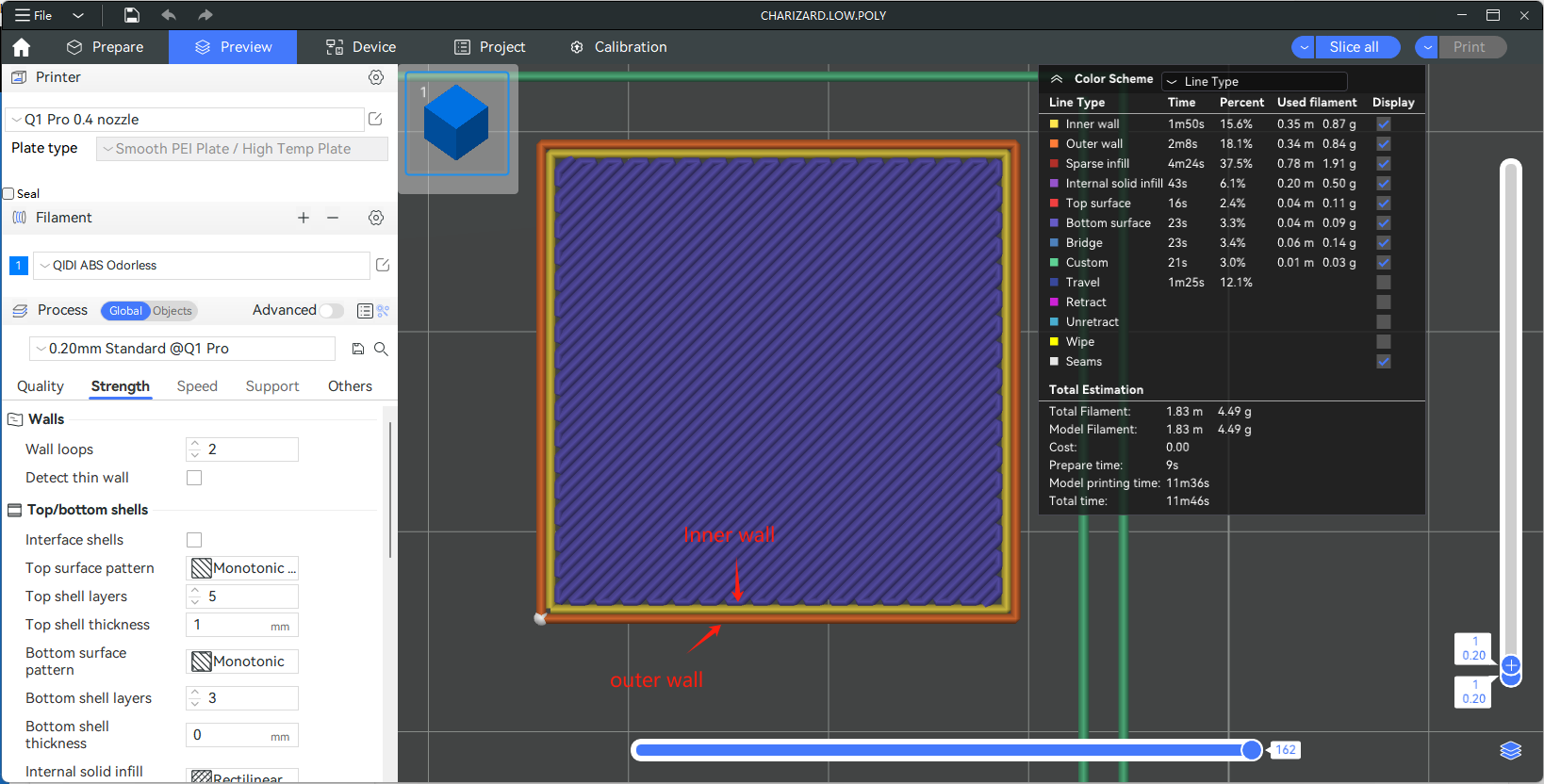
Slicing and printing of 3D models is essentially slicing a 3D model into many layers, and then printing layer by layer into a three-dimensional model. Each of these layers can be viewed as a polygon. The wall generator is responsible for generating wall paths for each layer of polygons.
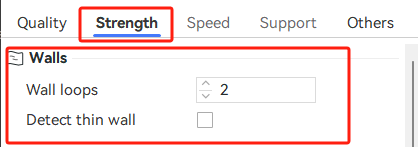
There is also a parameter called "Wall loops" to adjust the number of walls.


¶ How to Select the Wall Generator?
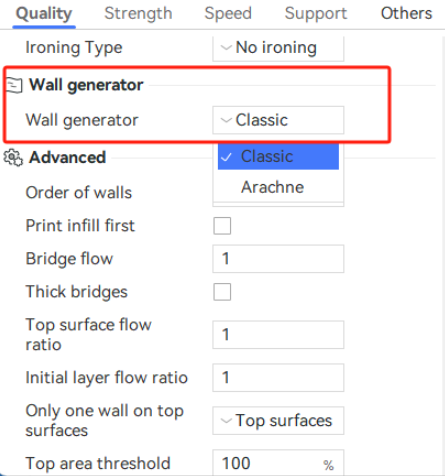
You can select Wall Generator in Process - Quality, which comes in two types: Classic and Arachne. These two kinds of walls use different algorithms to generate the path of the wall, and each has advantages and disadvantages.

¶ Classic
-
Advantage
If the printing paths are continuous, the uniform width of the classic wall paths ensures that the final printed model will only have one seam, resulting in better surface quality. -
Disadvantage
If the printing paths are discontinuous, the final printed model's surface will exhibit multiple seams.
Some models may contain very fine details that are too small to generate closed wall paths. Consequently, after slicing, these parts of the model may be missing or incomplete.
¶ Detect thin wall
In some scenarios, the “Detect Thin Wall” feature can solve this problem.
If this parameter is enabled, the shrinkage width during wall generation will decrease slightly to provide space for creating wall paths.
¶ Arachne
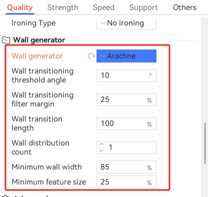
When you select the "Arachne" wall generator, some parameters will appear for adjustment, and the specific explanation is as follows:

-
Wall transitioning threshold angle:
When to create transitions between even and odd numbers of walls. A wedge shape with an angle greater than this setting will not have transitions and no walls will be printed in the center to fill the remaining space. Reducing this setting reduces the number and length of these center walls, but may leave gaps or overextrude。 -
Wall transitioning filter margin:
Prevent transitioning back and forth between one extra wall and one less. This margin extends the range of extrusion widths which follow to [Minimum wall width - margin, 2 * Minimum wall width + margin]. Increasing this margin reduces the number of transitions, which reduces the number of extrusion starts/stops and travel time. However, large extrusion width variation can lead to under- or overextrusion problems. It's expressed as a percentage over nozzle diameter. -
Wall transition length:
When transitioning between different numbers of walls as the part becomes thinner, a certain amount of space is allotted to split or join the wall segments. It's expressed as a percentage over nozzle diameter. -
Wall distribution count:
The number of walls, counted from the center, over which the variation needs to be spread. Lower values mean that the outer walls don't change in width. -
Minimum wall width:
Width of the wall that will replace thin features (according to the Minimum feature size) of the model. If the Minimum wall width is thinner than the thickness of the feature, the wall will become as thick as the feature itself. It's expressed as a percentage over nozzle diameter. -
Minimum feature size:
Minimum thickness of thin features. Model features that are thinner than this value will not be printed, while features thicker than the Minimum feature size will be widened to the Minimum wall width. It's expressed as a percentage over nozzle diameter.
¶ How Arachne mode works?
he Polygon converts from 2D to 3D, and then it can get the wall paths by the layer cut. If you are interested in it, you can check the article about Framework for Adaptive Width Control of Dense Contour-Parallel Toolpaths in Fused Deposition Modeling - ScienceDirect.