¶ Support style
QIDISlicer offers three different support styles:
- Grid
- Snug
- Organic
Once the print is complete, depending on the model geometry and the material used, the support structure is often easy to remove by hand. For areas that are harder to reach, you can use pliers for a better grip. A scalpel or utility knife can also be used to cleanly remove any support structures that are stuck to the model.
¶ Support mode
QIDISlicer provides three support modes:
-
Everywhere
Supports can be generated both from the print bed and from the surfaces of the model itself as needed. This ensures that all overhangs and parts of the model suspended in mid-air are supported. However, small imperfections might appear on the surface where the supports originated.
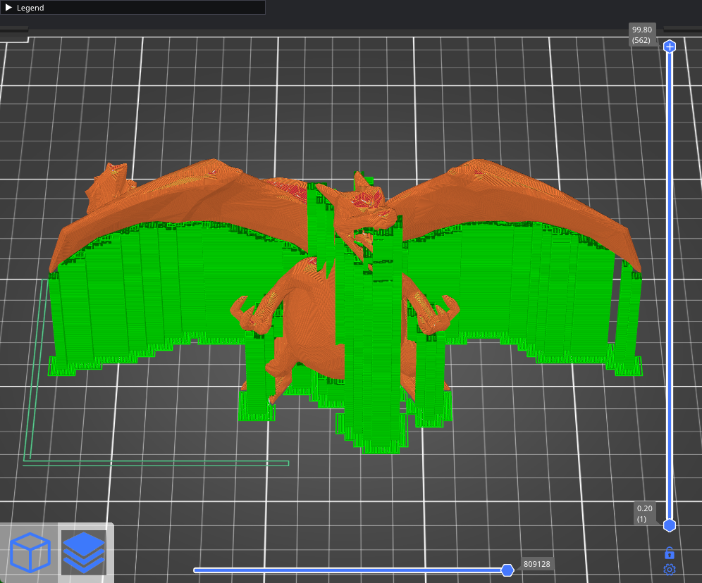
-
Support on build plate only
Creates supports only where the base is in contact with the print bed.
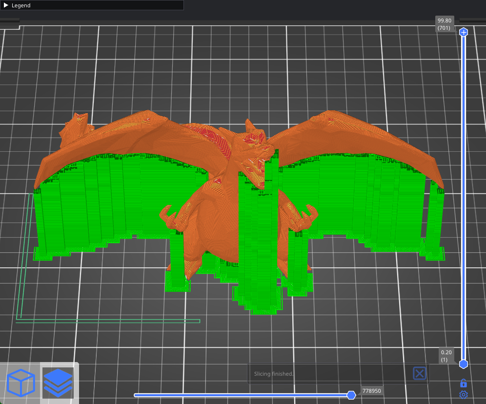
-
For support enforcers only
Support generation is enabled only in areas marked with a Support enforcer. This mode is essentially a shortcut to turning on Print settings - Support material - Generate support material while disabling Auto-generated supports.
¶ Supports on/off for individual models
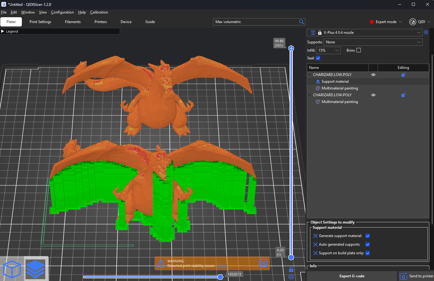
You can print multiple objects at once, each with its own unique support settings. By default, all models follow the global settings. However, you can override these by right-clicking on a model in the 3D view and selecting Support material. Alternatively, you can right-click on the edit icon in the Object list.
A new window, called Object settings to modify - Support material, will appear in the right panel. Changes made here will only affect the selected object and its instances. To revert to global settings, simply click the blue cross icon.
¶ Support enforcer/blocker
Automatic supports can sometimes appear in hard-to-reach places, requiring tedious removal. If you believe certain parts of the model could be printed without supports, but neither the Overhang threshold setting nor Support on build plate only solves the issue, you can manually adjust the supports.
Right-click on a model and choose either a Support blocker or Support enforcer..
-
Simple mode - Enforcers/blockers are always box-shaped
-
Normal mode - Box/Cylinder/Sphere/Slab shapes
-
Expert mode - Option to load external geometry as a blocker/enforcer
Support blockers and enforcers can be manipulated using the familiar Move, Rotate, and Scale tools. They can also be duplicated quickly using copy & paste.
¶ Support blocker
Support blockers are useful when you're satisfied with the automatic supports but wish to remove some of them. Place blockers where the supports meet the object, and the rest of the support structure beneath will be removed automatically.
¶ Support enforcers
Support enforcers are helpful when only certain parts of the model need support, but the automatic algorithm has placed supports all over the object. When using support enforcers, don't forget to switch the support mode to "For support enforcers only".
It's less common, but you can also use support enforcers with automatic support generation enabled.
A useful feature of support enforcers is to split long bridges into shorter segments by placing a support in the middle of the bridge. This allows for near-perfect bridges while making the supports easier to remove.
¶ Generate support material
Supports are disabled unless a model has an overwrite for this setting.
¶ Auto-generated supports
When disabled, overhang detection is turned off, and only support enforcers will generate supports.
¶ Overhang threshold
The Overhang threshold defines the steepest angle (measured from the horizontal plane) that can be printed without support material (90° = vertical
Adjusting this value is a quick way to control the amount of generated support. A lower value results in fewer supports.
| Overhang threshold:15 | Overhang threshold:30 | Overhang threshold:50 |
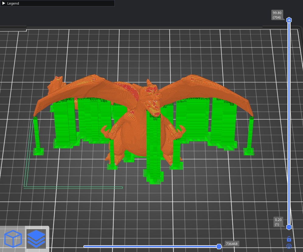
|
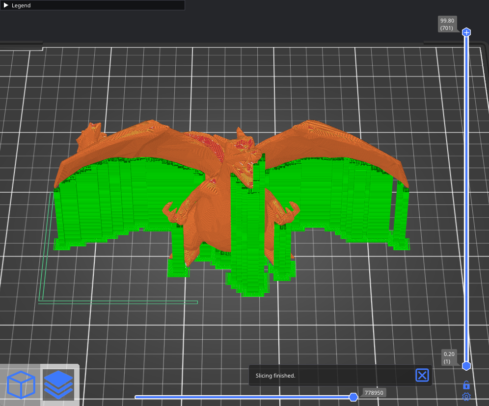
|
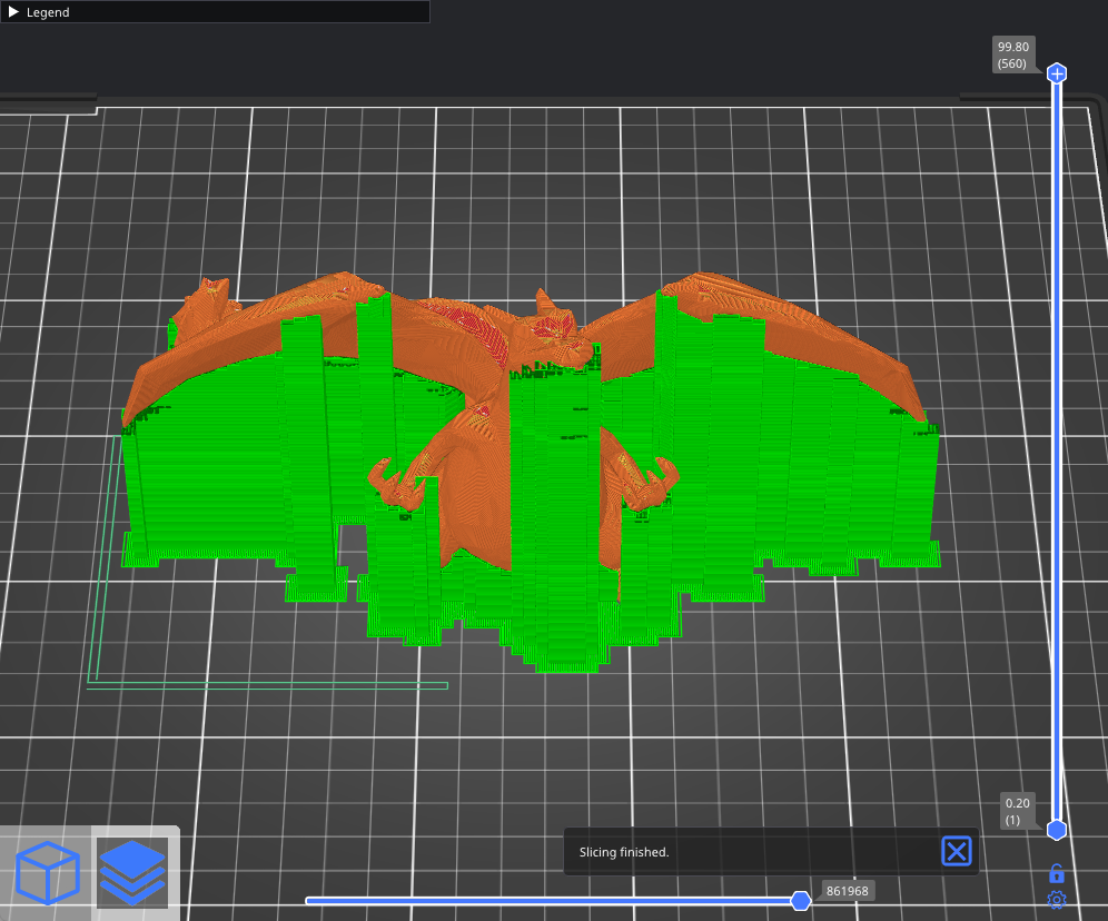
|
¶ Enforce support for the first
This setting generates support material for the specified number of layers from the bottom, regardless of the normal support material settings or any angle threshold. It’s particularly useful for improving adhesion for objects with very thin or poor contact with the build plate.
¶ Raft layers
The object will be raised by the specified number of layers, and support material will be generated underneath it. Once the print is finished, you can grab the raft and peel it away from the part.
¶ Raft contact Z distance
The vertical distance between the raft and the object. This setting is ignored when using soluble interfaces.
¶ Raft expansion
This setting defines the expansion of the raft in the XY plane to improve stability.
¶ Style
The style and shape of the supports can be adjusted. The default Grid supports have well-defined minimum areas, providing strong stability, but they may leak out into unsupported regions along the object's walls. Snug supports maintain the shape of the overhang, preventing leaks to the walls but may result in lower stability for tall, thin support pillars.
| Grid | Snug |
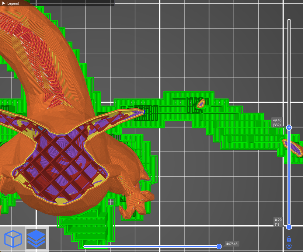
|
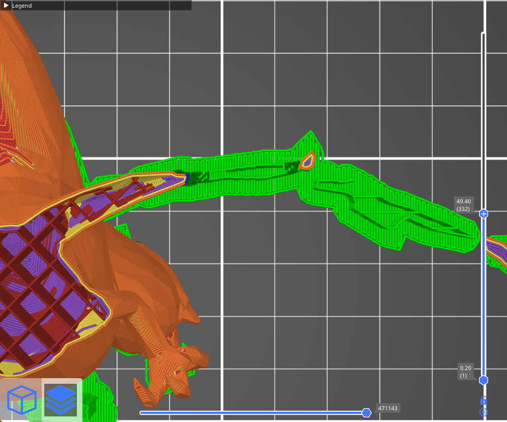
|
Organic supports offer a completely different approach. Support branches grow from the sides and automatically become denser beneath areas that need support. Organic supports are easy to remove, leave no scars on the surface, and are quick and cost-effective to print. For more details, refer to the Organic Supports.
¶ Top contact Z distance
This is the vertical distance between the object and the support material interface. Setting it to 0 will prevent the use of bridge flow and speed for the first layer of the object.
Values between 50-75% of the layer height tend to work well.
¶ Bottom contact Z distance
Similar to the Top Contact Z Distance, but affects the gap at the bottom of the support tower (when supports start on top of a model instead of on the build plate).
¶ Pattern
-
Rectilinear
The default pattern, generally the easiest to remove. -
Rectilinear grid
Stronger and less prone to breaking during printing compared to rectilinear infill, but harder to remove. -
Honeycomb
Sturdy, but somewhat difficult to remove.
¶ With sheath around the support
Creates a single perimeter around the supports, making them sturdier but harder to remove.
¶ Pattern spacing
The spacing between support material lines. Increasing this spacing makes support removal easier, but too much spacing may cause the bridges to sag and create imperfect connections with the model.
¶ Pattern angle
Rotates the infill pattern angle on the horizontal plane.
¶ Closing radius
Only for Snug supports. Gaps smaller than the closing radius will be filled.
¶ Top interface layers
Interface layers create a more uniform surface between the object and support material. These layers should be printed with a denser pattern than the non-interface layers to maximize surface contact and prevent sagging while minimizing print time and material usage.
¶ Bottom interface layers
Similar to top interface layers, but affects the bottom interface layers when supports start on top of a model instead of the print bed.
¶ Interface pattern spacing
Defines the spacing between interface lines. Set to 0 for a solid interface.
¶ Interface loops
When enabled, the top layer of supports is covered with loops (continuous polylines).
¶ Support on build plate only
Supports will only be generated starting from the print bed. Enabling this option is a quick way to eliminate excess supports, particularly for organic shapes. Be sure to check the preview and verify that all parts are either supported or have an overhang angle that the printer can handle.
¶ XY separation between an object and its support
Sets the gap between the model and the supports. A larger XY separation decreases the contact area, making the supports easier to remove and less likely to fuse with the model.
¶ Don’t support bridges
Prevents support material from being generated under bridged areas.
¶ Synchronize with object layers
Ensures that supports are printed at the same layer heights as the model. This is particularly useful with multi-material printers, where extruder switching is costly.
This option can only be enabled when using soluble supports (contact Z distance set to 0).