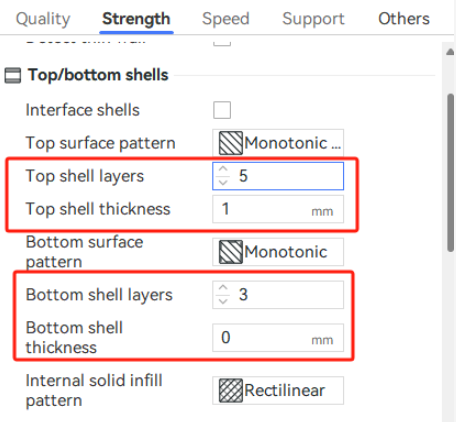
¶ Introduction
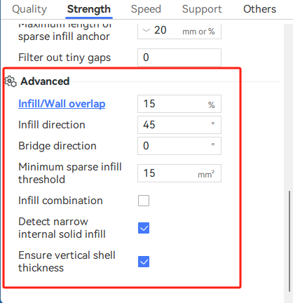
you can set some advanced parameters related to strength in Process - Strength - Advanced.
¶ Infill/Wall overlap
The Infill area is enlarged slightly to overlap with the wall for better bonding. The essence of this parameter is to control the overlap of all the infill lines (here "infill" refers to all the horizontal directions of the shells, including sparse infill/internal solid infill/top surface/bottom surface/bridge) and the vertical shells (inner and outer walls), which can increase or reduce the riveting between them. The percentage value is relative to the line width of sparse infill. The default value is 15%.
-
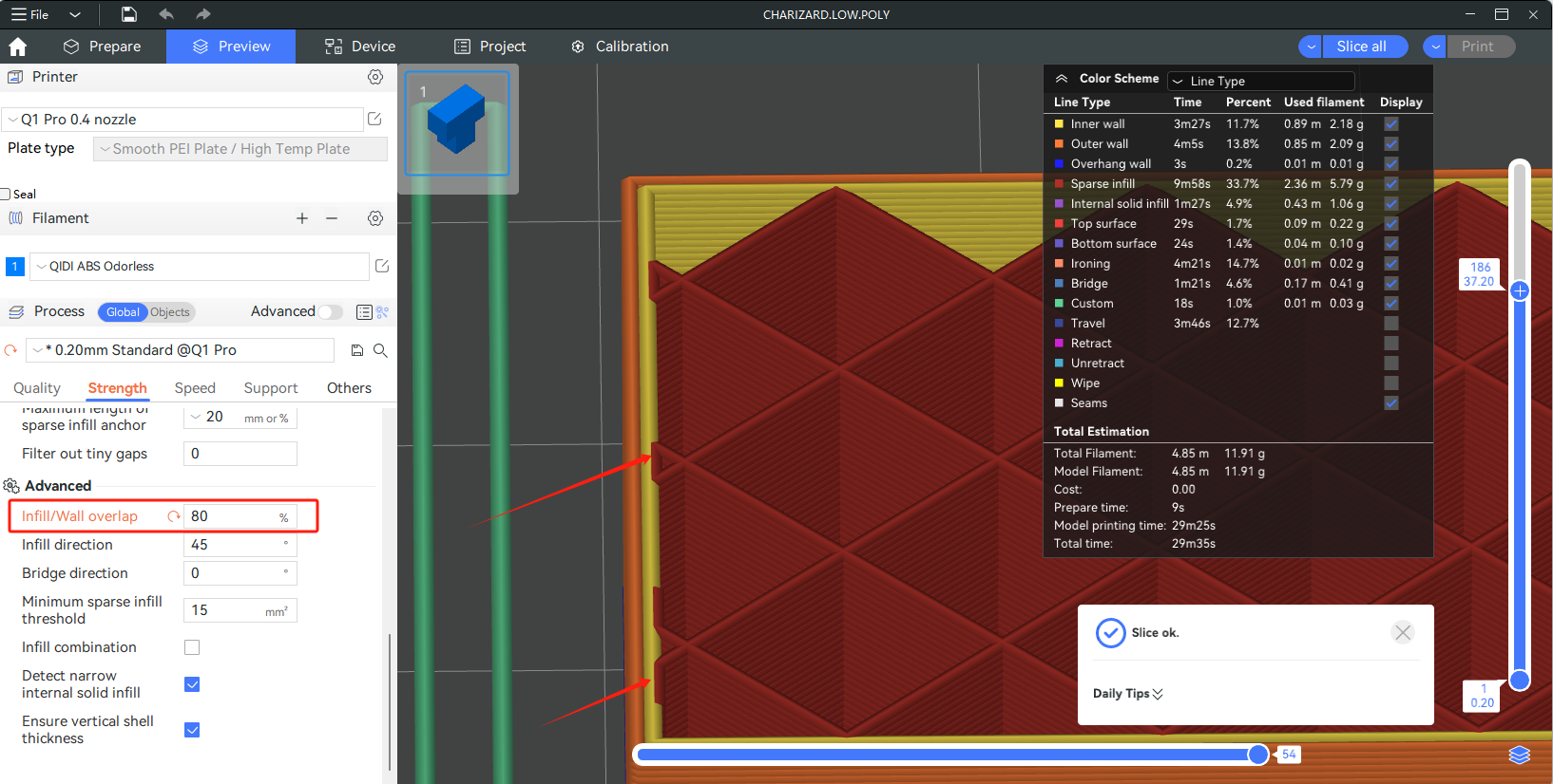
When the overlap is set to 80%, it can be seen from the figure below that 80% of the width of sparse infill lines overlaps with the inner wall. If the overlap rate is too high, the model's surface will bulge, affecting appearance.
-
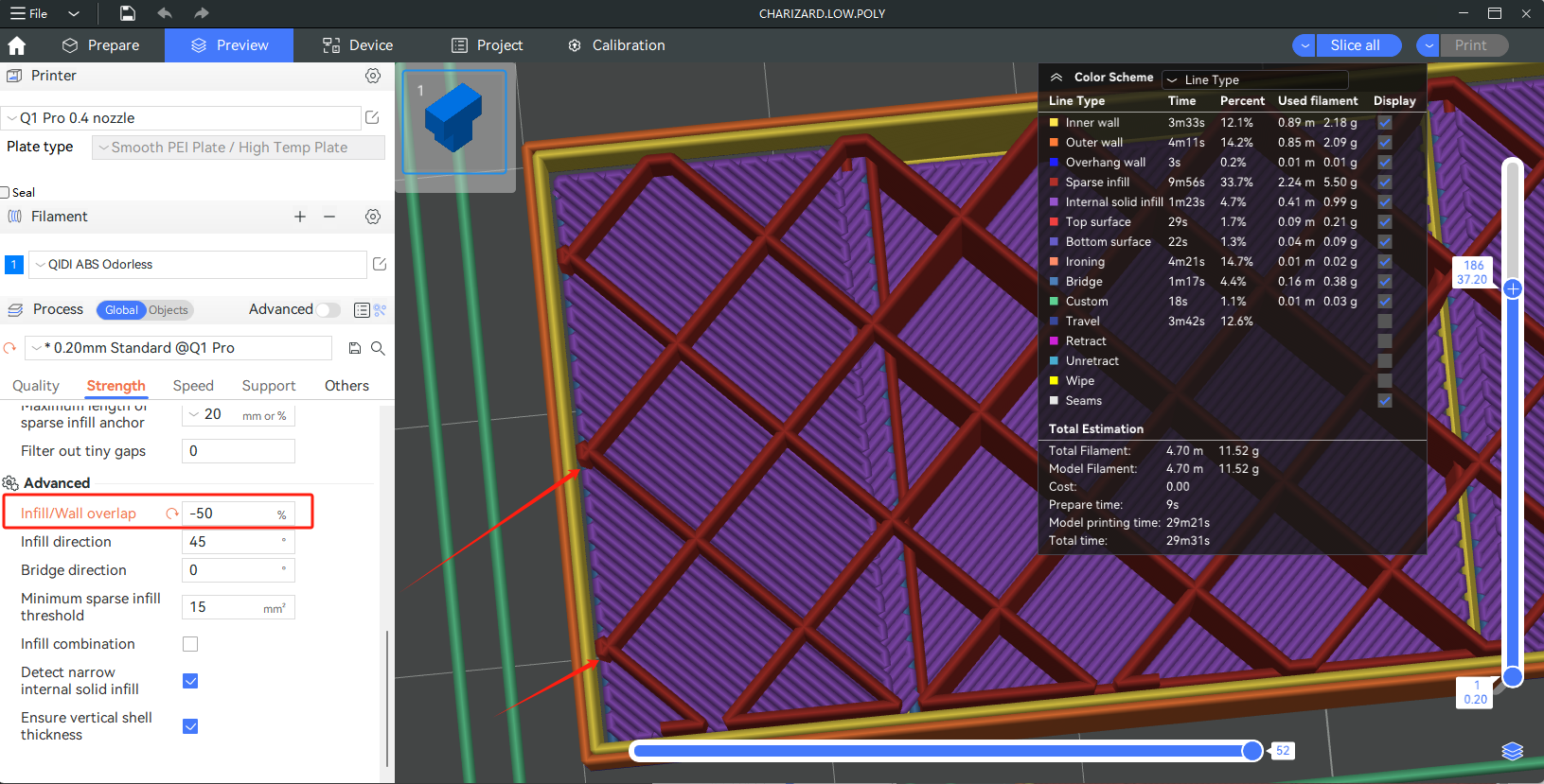
The overlap rate can also be set to a negative value, which means that the fill and wall do not overlap at all. For example, if the overlap rate is set to -50%, it can be seen from the figure below that there is no overlap between the sparse infill and the inner wall, and there is a 50% line width gap between them.
However, if the overlap rate is set to negative, it may affect the appearance of the top and bottom surfaces, because the top and bottom lines will not be riveted to the wall.
¶ Infill direction
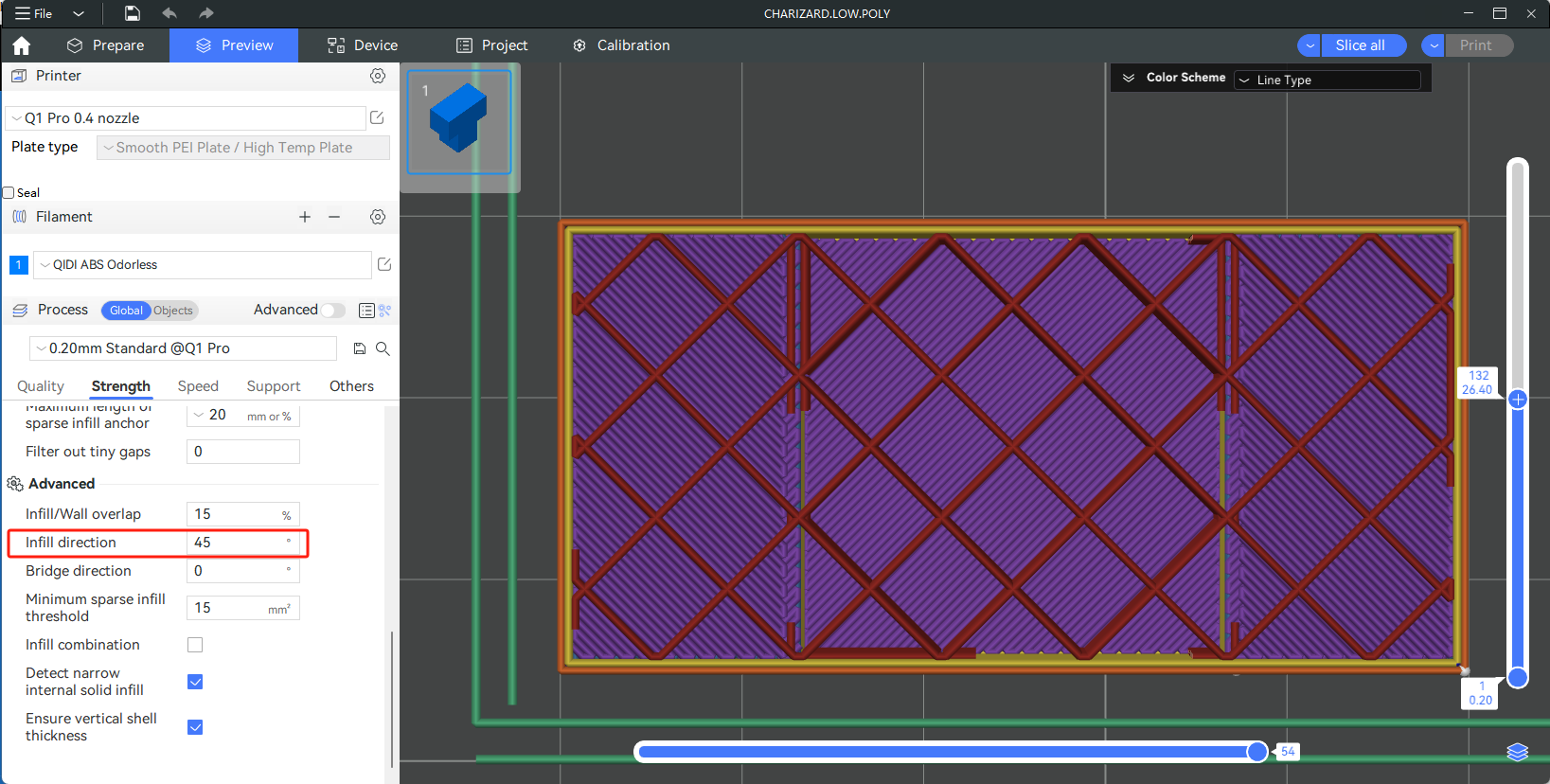
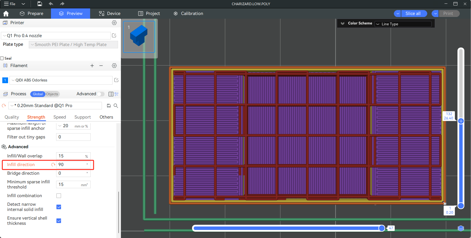
Angle for sparse infill pattern, which controls the start or main direction of the line. This parameter also adjusts the direction of all infill lines, including top surface, bottom surface, sparse infill, and internal solid infill (except bridge).
-
Infill direction 45°:
-
Infill direction 90°:
¶ Bridge direction
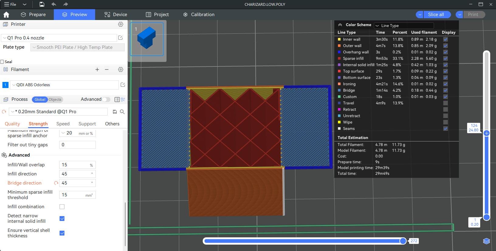
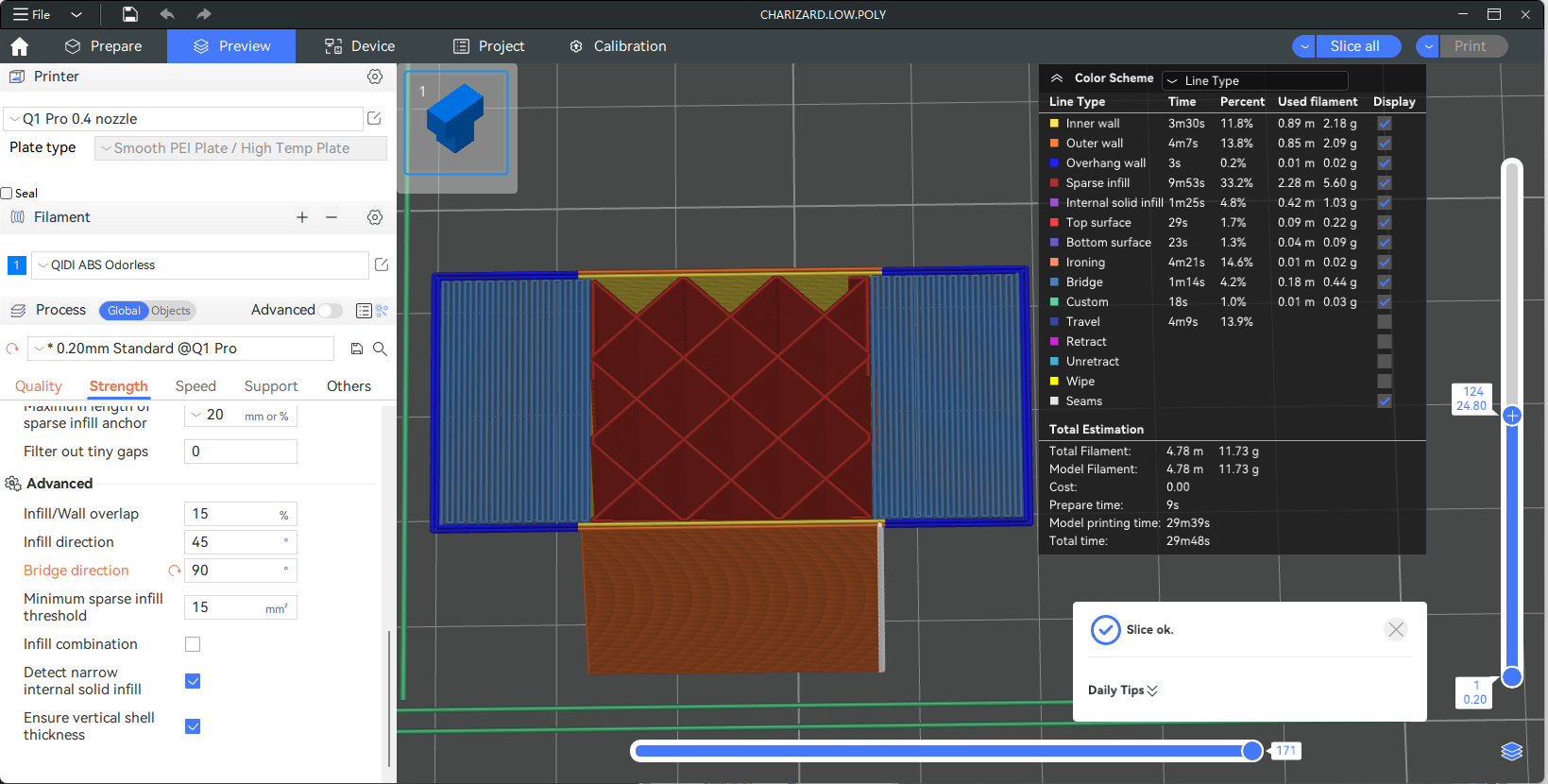
Set the bridge direction for the external bridge. If set to 0, the Angle will be calculated automatically. Otherwise, the external bridge will use the provided value. 180° indicates 0°.
-
Bridge direction 45°:
-
Bridge direction 90°:
For more information on bridging Settings, please refer to the wiki: Bridge settings.
¶ Minimum sparse infill threshold
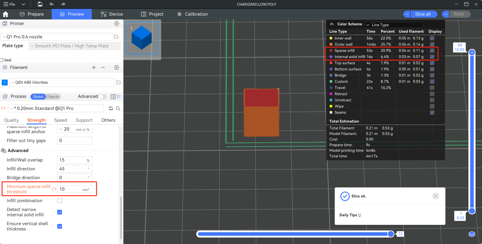
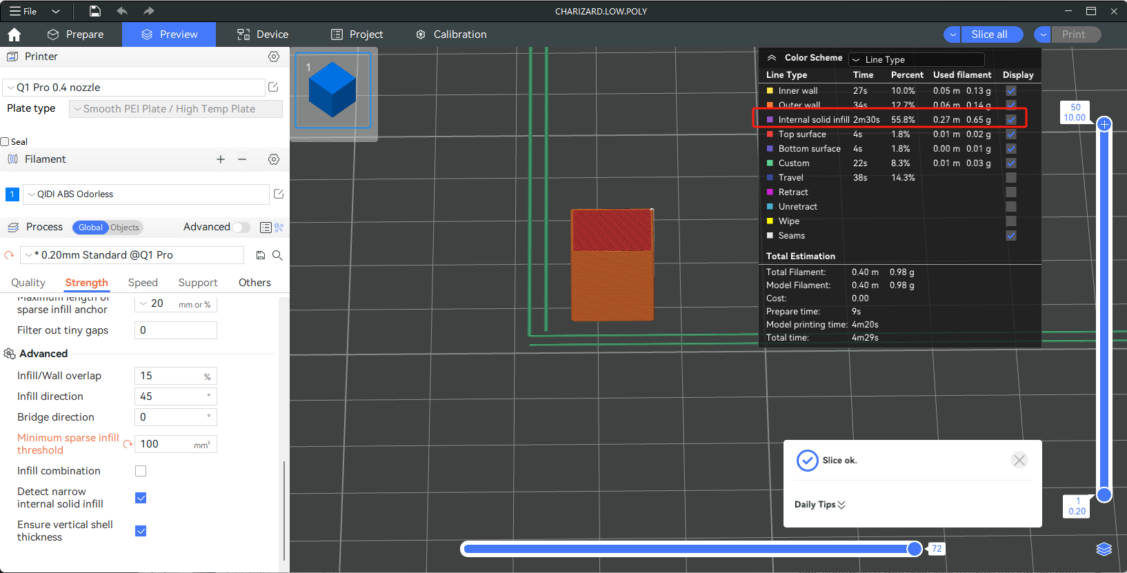
The sparse infill area smaller than the threshold value is replaced by internal solid infill. In other words, if the area of the internal infill area is less than this set value, the line type of the area will be filled with internal solid infill, otherwise it will be sparse infill. The main purpose is to improve the strength and fill the narrow area with solid infill to avoid too low strength leading to fracture.
Let's use a 1cm³ cube as an example.
-
Minimum sparse infill threshold 10mm²
-
Minimum sparse infill threshold 100mm²
¶ Infill combination
Automatically Combine sparse infill of several layers to print together to reduce printing time. Wall is still printed with the original layer height. The logic of the infill combination is to take the maximum integer multiple of the wall layer height as the height of the sparse infill within the range of no more than the nozzle diameter.
For example, select the 0.4mm nozzle preset. After enabling the infill combination, the wall with layer height of 0.08mm and 0.2mm, the sparse infill layer height will be 0.4mm (the former prints 1 layer of sparse infill for every 5 layers, while the latter prints 1 layer of sparse infill for every 2 layers). Use 0.36mm sparse infill layer height for 0.12mm wall layer height (printing 1 layer of sparse infill for every 3 layers). Use 0.32mm sparse infill layer height for 0.16mm wall layer height (printing 1 layer of sparse infill for every 2 layers). However, due to exceeding the nozzle diameter after taking integer multiples, there is no suitable sparse infill layer height for the 0.24mm and 0.28mm layer heights preset, so the infill combination cannot be used.
¶ Detect narrow internal solid infill
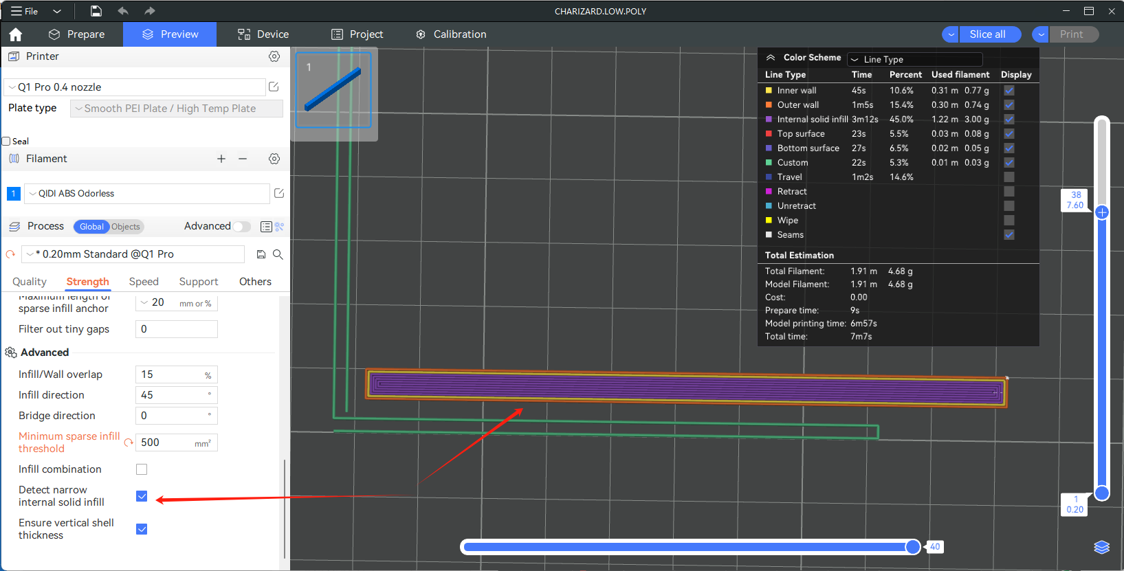
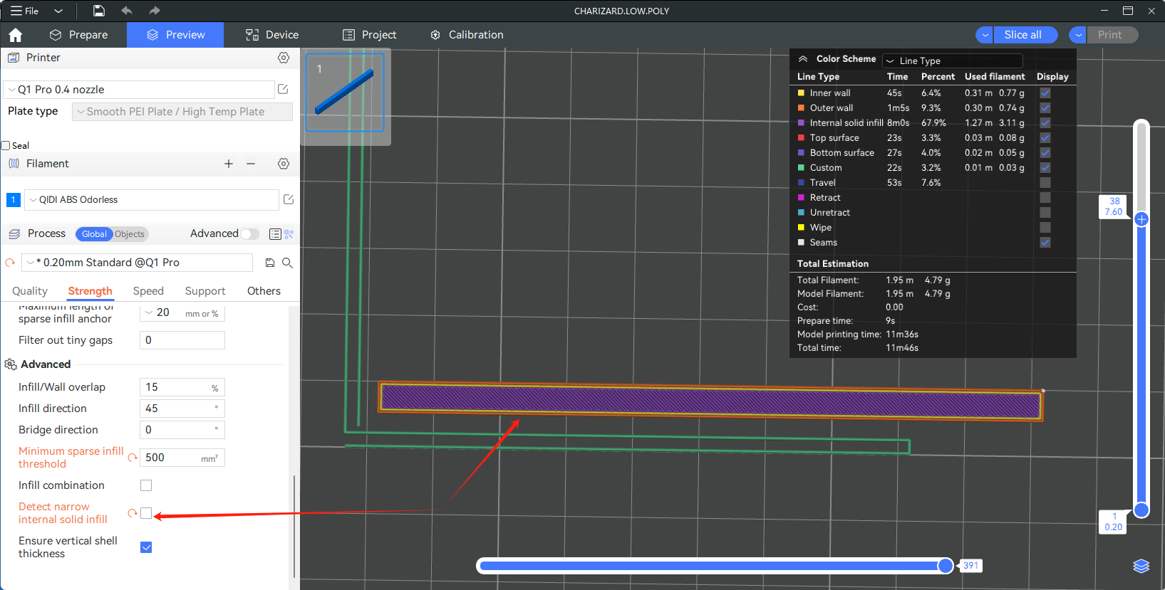
This option will auto detect narrow internal solid infill area. If enabled, concentric pattern will be used for the area to speed printing up. Otherwise rectilinear pattern is used defaultly.
¶ Ensure vertical shell thickness
Add solid infill near sloping surfaces to guarantee the vertical shell thickness (top+bottom solid layers). The vertical shell thickness that needs to be ensured depends on the set top shell thickness (number of layers) and bottom shell thickness (number of layers).
