¶ Support Introduction
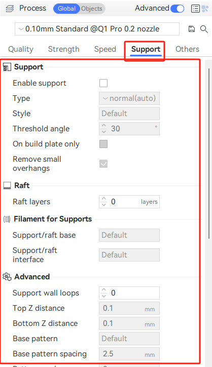
QIDI Studio has a full page of support settings, as shown below.
¶ Support types
There are two basic types of support: normal and tree.
- normal support
Directly projects the overhangs down to the heat bed, and gets the support body. - tree support
samples the overhangs to get the so-called nodes, each node is represented as a circle. And then the nodes are propagated down to the heat bed. During propagation, the circles may be enlarged to get better strength and may be moved away from the object so the supports are less likely to collide with the object.
¶ Type of support
There are two basic types of supports: normal supports and tree supports.
- Normal support:
The suspended part of the model is directly projected downward onto the hot bed,and the support is draw on this basis to support the suspended part. - Tree support:
Overhangs are sampled to obtain nodes, each representing a circle. The node the propagates down to the hot bed, and during propagation, the circle can expand for better intensity, and it can move away from the model. Therefor, the tree support is less likely to interfere with the model while maintaining the support strength.
In the Support Settings page, QIDI Studio provides four types of supports, which are:
- Normal (Automatic): Automatically detects the normal support of the suspended part.
- Tree (Automatic): Automatically detects the tree support in the overhang.
- Normal (Manual): Generate normal supports only on the support force generation surface (you need to draw the support manually, please refer to Support Painting Guide for details).
- Tree (Manual): Generates a tree support only on the support force generation surface (you need to draw the support manually, please refer to Support Painting Guide for details).
¶ Support style
Both normal and tree supports have different styles to further adjust the final support structure. Normal support has two styles:
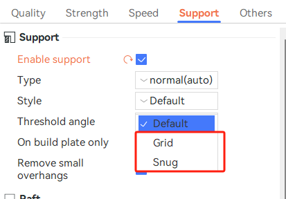
- Grid: the support region is expanded and normalized to rectangles. This is the default style of normal support.
- Snug: the support region is NOT expanded, but tightly aligned with the overhang areas. This style is useful when the expanded supports have any side effects, such as in the following case.
Tree support has three styles:
- Tree Slim
This features an aggressive branch-merging strategy. As a result, a much smaller support volume is generated without sacrificing strength (by automatically increasing the wall count and using smoother branches). - Tree Strong
This features a relatively conservative branch-merging strategy, resulting in connected strong tree branches, sometimes difficult to remove.
Tree Organic: this features organic shaped tree branches, and also aggressive branch-merging strategy. This style is introduced Cura Slicer, then ported to Prusa Slicer, and then ported by us. - Tree Hybrid
The current default style, which is the hybrid of tree strong and normal grid. Below the big flat overhang regions, normal grid supports are generated. Otherwise, it will generate the tree strong supports. - The Origanic
A variant of tree-like supports, transplanted into PrusaSlicer, which can save more material and facilitate disassembly.

¶ Common options
¶ Threshold angle
The threshold angle is the maximum slope angle that needs support. If a surface's slope angle to the horizon is less than this threshold value, support will be generated when the support type is auto.
The larger this angle is, the more supports will be generated. The default threshold angle is 30 degrees. For most materials, this is a safe angle to print without support.

¶ Raft
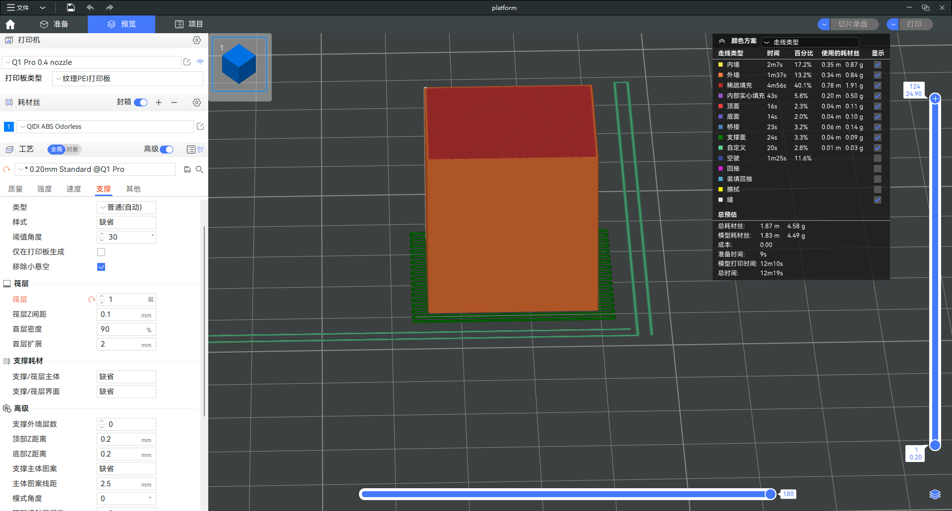
Raft is a type of support, which is used to generate support at the bottom of the model to lift it up. Usually, when printing materials such as ABS that are prone to warping, then you can enable the raft.
-
The raft contact Z distance:
Represents the distance between the top of the raft layer and the model. -
The first layer density:
Represents the density of the first layer of the raft and the support -
The first layer expansion:
can be used to expand the first raft and support layer, improving the bed adhesion.
¶ Support filament
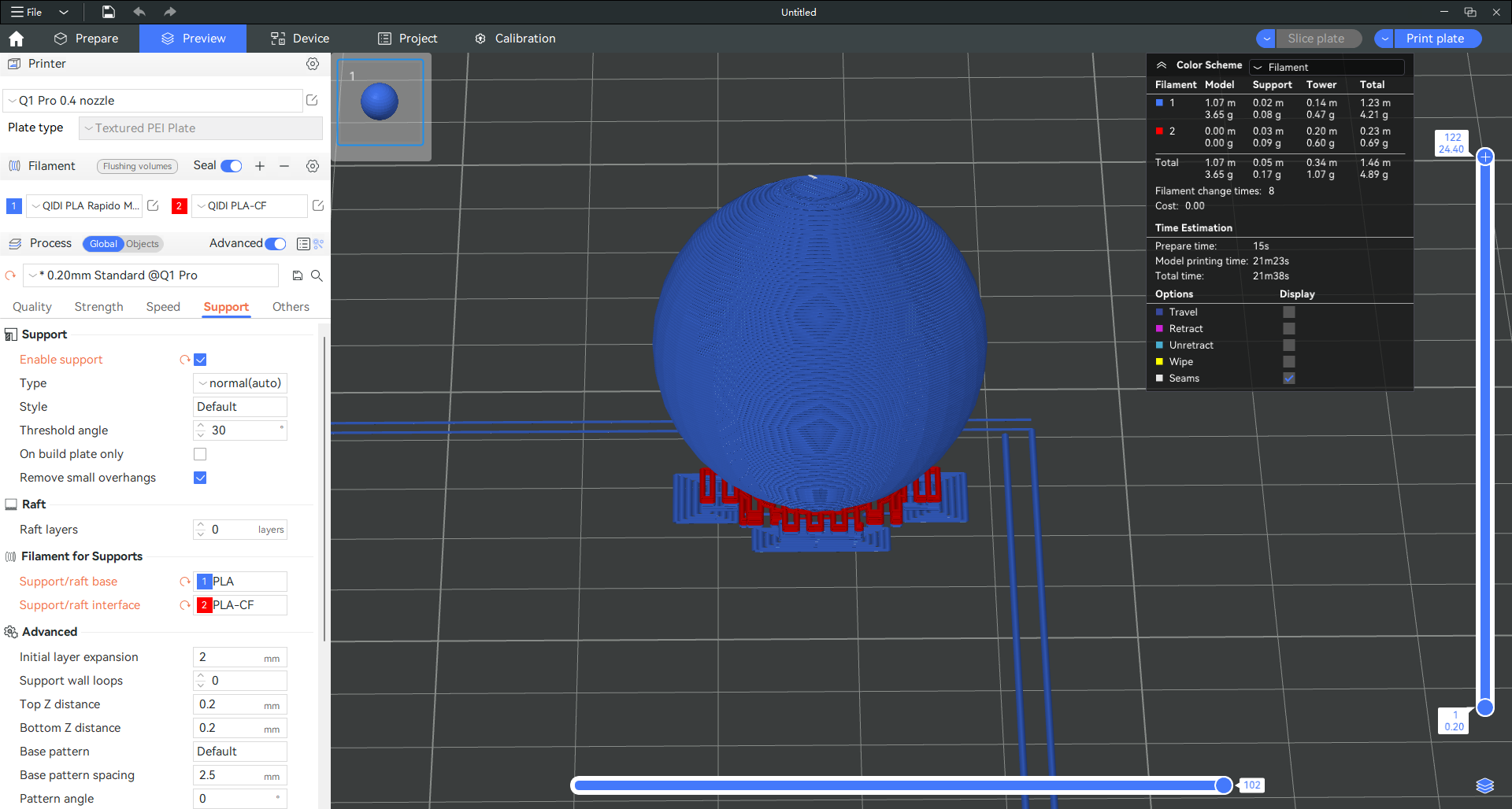
The support consists of two parts: the support body and the support surface. The support surface is the part that connects with the model, and the rest is the support body.
These two sections can be set up for different types of consumables. When the default time indicates that no filaments are specified, the filaments printed at the current layer are used to reduce the time for replacing consumables.
¶ Top Z distance & Support/object XY distance
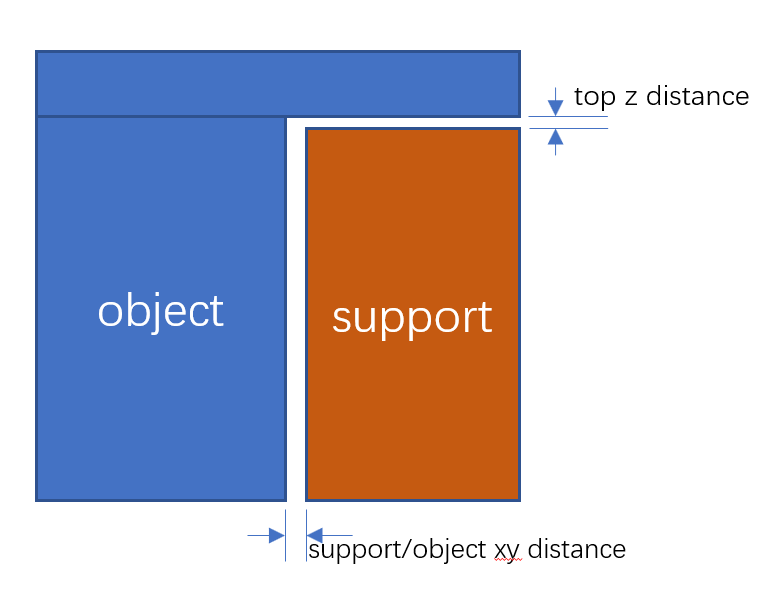
The XY distance between the support and the object and the top Z distance from the support top to the object are shown below.
When setting to 0, the support filament is assumed to be support material.
Note: When printing a model with support structure, it is necessary to remove the support structure within 2 hours to prevent it from being difficult to remove or remaining residues on the prints after being damp and softened.
¶ Base & interface pattern settings
¶ Base pattern
This is the infill pattern of the support base. There are currently 5 patterns, as shown below.
-
Rectilinear:
The most commonly used support and default pattern for normal support, which usually goes in two directions (left to right, front to back)

-
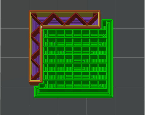
Rectilinear grid:
Similar to rectilinear, except it alternates the direction of every layer, so its strength is much better but can be harder to remove.
-
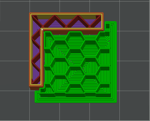
Honeycomb :
Very different than the other two, and is a good balance of strength and stability for taller support structures.
-
Lightning
Not support. -
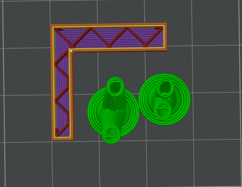
Hollow
A default pattern for tree support, which means no infill at all.
¶ Base pattern spacing
- For rectilinear and rectilinear grid patterns, this is the spacing between base pattern lines.
- For the honeycomb pattern, this is the radius of each honeycomb cell. So when this value is set to 0, the honeycomb pattern degenerates to rectilinear.
¶ Pattern angle
Set the rotation Angle of the support pattern on the horizontal plane.
¶ Top interface layers
The number of top interface layers. The overhang quality can be improved if we increase this value, at the cost of slightly more material.
¶ Interface pattern
The line pattern of interface layers. There are currently 3 patterns available:
- Rectilinear:
Suitable for most cases. - Concentric:
Concentric circular pattern, which is stronger on non-planar surfaces and useful with support materials. For best surface quality we can set a very small interface spacing (e.g. 0) when using cocentric pattern and support material. - Default:
The default pattern with support material is rectilinear and concentric.
¶ Tree support-only options
-
Tree support branch distance:
The distance between neighboring tree support nodes. A smaller value means higher sampling density on the overhang surface and, therefore better surface quality, at the cost of more removal difficulty. -
Tree support branch diameter:
The initial diameter of the tree support node. A larger value means stronger tree supports, also more difficult to remove. -
Tree support branch angle:
The angle of tree branches stretching out. Larger values mean that tree support branches can be printed more horizontally, with a higher ability to avoid objects and extend further out. -
Tree support with infill:
Infill will be generated in the tree support base if enabled. This makes tree support very strong, so we disable it by default. But if you are using some weak material, suach as PLA, it's suggested to enable this option. -
Max bridge length:
the max allowed bridging length for overhangs. if an overhang is rectangular, it is regarded as a bridge. A short bridge can be printed well enough without support, because the two ends of the extrusion lines are well supported. The max allowed bridging distance may be different for different materials. When a bridge is large than max bridge length, it's divided into equal segments and only the contacting points are supported.
¶ normal support

¶ tree support
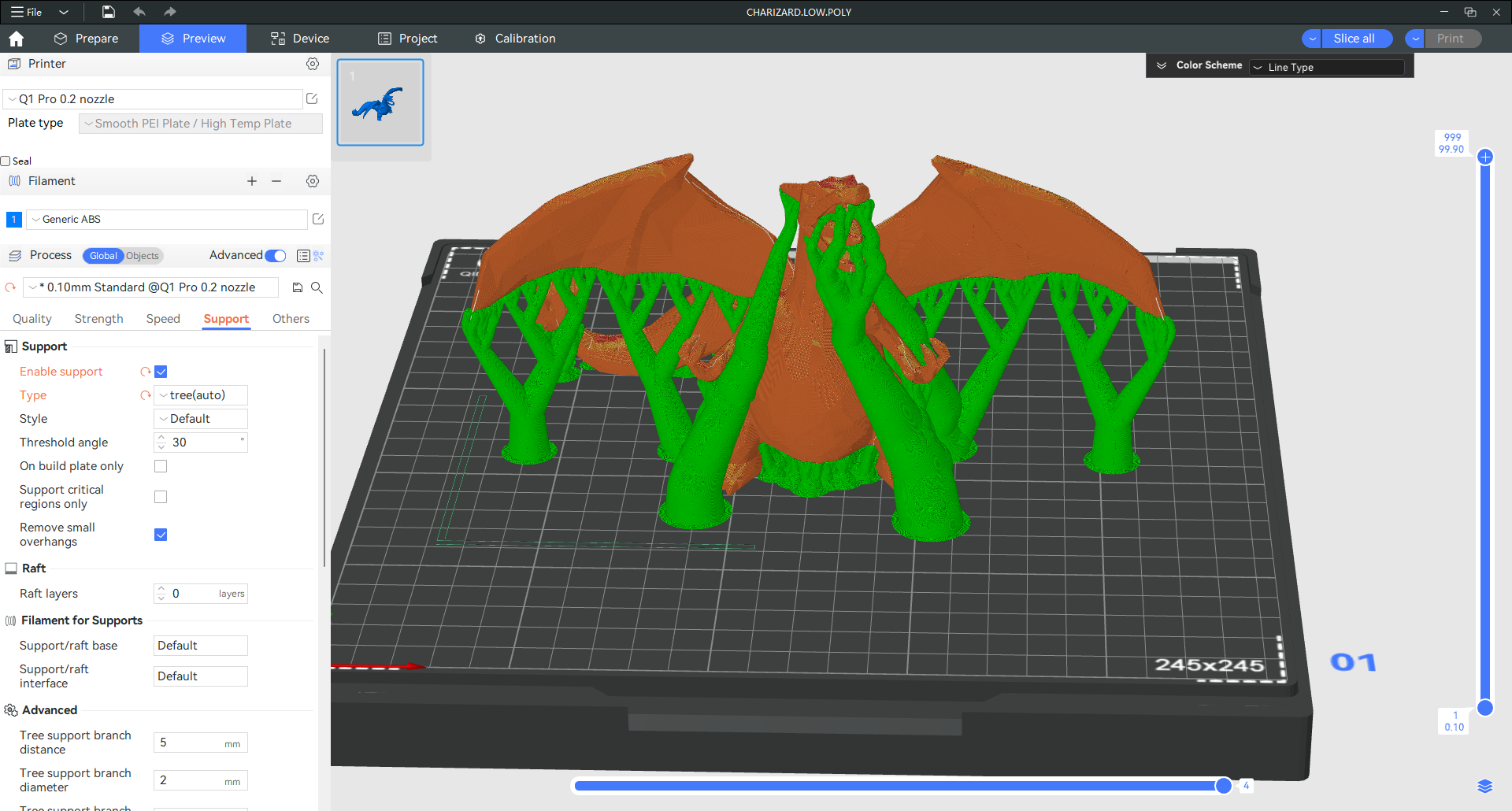
Model from Charizard LOW-POLY